|
Below are the procedures that I used in performing the replacement of six of
my fuel injectors. I put them on this web page to serve as guidance for you,
but do not guaranty the results nor do I proclaim this is
the correct procedure, though I reference the Nissan Factory Service
Manual, hereinafter ("FSM"), throughout. If you have any doubt on your
capability in performing this replacement, take your car to a certified
mechanic.
What you need:
1. Upper intake
manifold gasket; part number 14033-89E00
2. Lower intake manifold gasket;
part number 14032-89E01
3. Throttle body gasket; part number
16175-89E10
4. A.A.C valve gasket
5. New / remanufactured fuel
injectors
a. see the picture below, which depicts the
two injectors with different connectors.
b. The 90 -91
injectors have the metal clip (smaller) harness connector and the 92-94's have
clip-type (bigger) harness connector.
c. Also, Nissan made
both blue and black dot injectors for our cars. I have been told you can use
either one, but can't mix and match. I doubt it would hurt mixing and matching
though, just so long as you get the right one for your car. The dot is on the
harness connector.
d. I picked up my remanufactured units
for $37.95/ injector after the core deposit refund from Direct Automotive
Products (www.directauto.com)
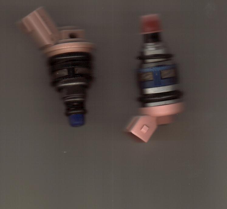
The injector on the left is a 92-94 injector, and the right is a 90-91,
and probably an 89 too.
The steps I performed:
1.
Release fuel pressure to zero
a. I did this by
unhooking the upper hose from the fuel filter after pulling the fuel pump
fuse
2. Separate the accelerator cables from the throttle
body.
a. they easily just slide off. Tilt the
butterfly valves back to get them.
b. Remove the cabling
and routing from the intake plenum.
3. Remove spark plug wires from spark
plugs.
4. Remove the intake elbow leading to the throttle
body.
a. there are three bolts, the middle one is the
longer one and routes the spark plug wires.
b. These bolts
are torqued at 13 - 16 ft lbs.
· For steps 6 - 9, basically remove necessary
hoses and vacuum lines so you can free the plenum for removal. I took notes on a
few of the items I might have forgotten when putting things back
together.
5. Remove the A.A.C. valve
a. there
are four 5 mm hex bolts holding this in. remove the harness connector
also.
b. There is an "S" shaped hose connecting the AAC
valve to the plenum, remove this also.
6. Disconnect throttle
sensor
7. Disconnect the P.C.V. hoses behind the intake
plenum
8. Disconnect vacuum hoses under the throttle body, from the
E.G.R. control valve, master brake cylinder ,etc.
9. Remove the E.G.R.
flare tube
a. this is held on by two nuts. I think
they are 10mm in size.
10. Remove the upper intake
plenum
a. there are eleven six
millimeter hex bolts that hold down the plenum at 13 - 16 ft
lbs.
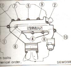
b. There is a special torque
sequence that I observed in both loosening them and tightening them down. Please
refer to the picture at the bottom of the screen for that sequence.
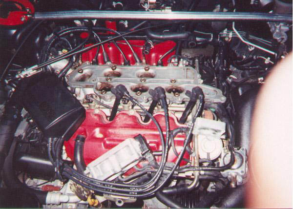 
Less the spark plug wires and
the throttle body (my procedure keeps it attached to the plenum), your engine
should look something like the above before taking the lower intake manifold
off. Pictures are courtesy of Matt Blehm.
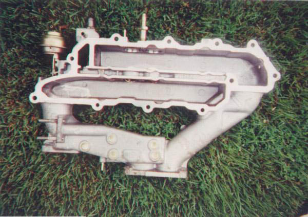
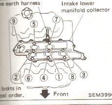
11. Remove the lower
intake manifold collector from the
engine.
a. Use the loosening
sequence below for taking the manifold off and putting it back on. Again,
reference the picture at the bottom of the screen.
12. Remove the engine
earth harness from behind the plenum.
13. Remove the fuel injector
harness wires
a. For the
92,93,94's this is easy, as you just apply pressure on the harness and
pull
b. For the 90 and 91's (and
presumably 89's) there is a metal wire clip that you must pull out or partially
out to remove the connector.
14. Remove fuel
injector(s)
a. I used a pair
of pliers and gripped them tightly, turning the injectors back and forth before
pulling upward. All came out somewhat easily, except my last
one.
b. There should be two O
rings per injector for the 90 -91 injectors. I am not sure the 92,93,94
injectors have two. The lower O ring will likely stay in the fuel rail hole upon
removal of the injector. Just stick your finger in and retrieve it. Be sure to
replace with new "O" rings, per the FSM.
15. Replace
injector(s)
a. I applied motor
oil to the O rings and carefully inserted the new fuel injector. Instead of just
pushing downward immediately, you should turn it back and forth, while applying
downward pressure. You will see and feel the injector seat in how it should
be. Before replacing, assure that the new ones spec out
correctly with regard to resistance. The range of resistance allowed by Nissan
is 10 –14 ohms.
16. Clean intake plenum, lower intake
manifold, and intake runners.
a. I used Carb clean and a Valvoline product. I sprayed a good amount of Carb
clean down the intake runners and used a cloth to wipe the dirt out. You may
want to try a toothbrush.
b. Be
sure to completely scrape away all remaining gasket material on both surfaces so
as not to allow an intake leak after assembly.
17. Reinstall all parts in
reverse order, keeping in mind the torque sequence and use the torque wrench so
as to tighten the following to these torque specifications, per the
FSM:
a. plenum hex bolts 13
- 16 ft. lbs.
b. lower intake
manifold hex bolts, 13 - 16 ft.
lbs.
c. A.A.C valve bolts -
4.6 - 6.1 ft lbs.
d. intake
elbow bolts 13 - 16 ft. lbs.
|